

Short answer
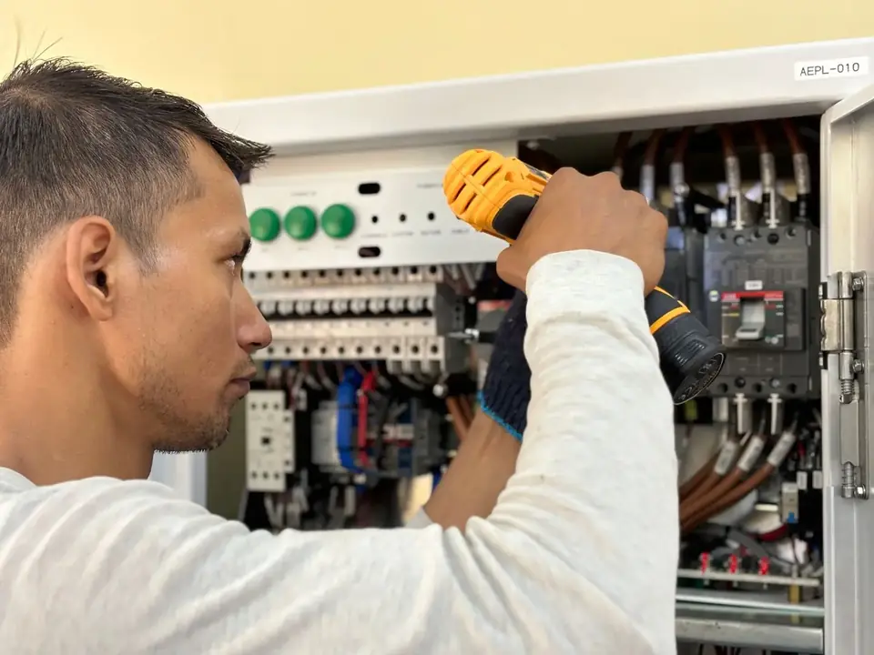
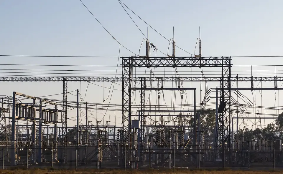
Factories measure earthing to confirm that fault currents and lightning have a safe, low-resistance path to ground, which protects people, equipment and production. The test is usually made with a fall-of-potential earth tester, and the report should show each electrode’s resistance, the method and conditions, and recommendations measured against the design target.
Why earthing matters in a factory
An earthing (grounding) system connects exposed metal parts, equipment frames and, where the design calls for it, the neutral point of the electrical system to the general mass of earth. It has to work on the day something goes wrong, which is why it is measured rather than assumed.
- Personnel safety: a low-impedance fault path lets protective devices disconnect a faulty circuit quickly and limits dangerous touch voltages on equipment.
- Equipment protection: surge protective devices, drives and electronic controls depend on a sound earth reference.
- Lightning protection: down conductors are only effective when their earth terminations can disperse the current.
- Static control: in plants that handle powders, solvents or flammable materials, bonding and earthing help prevent static build-up.
- Audits and insurance: client audits, insurers and management systems often ask for recent measurement records.
How earth resistance is measured
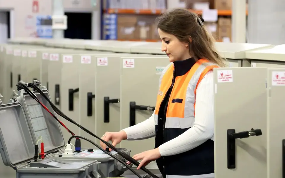
The most widely used method is the fall-of-potential (three-point) test. A calibrated earth tester injects a test current between the electrode under test and a remote current spike, and measures the voltage with a potential spike placed between them. Readings are taken at several positions of the potential spike; a stable plateau, commonly found at about 62% of the distance to the current spike in uniform soil, indicates a valid result.
- Clamp-on testing measures electrodes in multi-earthed systems without disconnecting them, but it needs a parallel return path and does not suit every arrangement.
- Soil resistivity testing, usually by the Wenner four-pin method, is used at the design stage to size new earthing networks.
- Continuity and bonding tests with a low-resistance ohmmeter confirm that equipment, structures and pipework are connected to the earthing system.
Safety first: opening a test link isolates an electrode from the installation. Do it only under a permit-to-work, after a risk assessment and, where needed, with the supply arrangements changed, and reconnect before leaving the pit.
When to test
Test frequency should follow your maintenance plan, the applicable standards and any insurer or client requirement. Beyond routine tests, measure:
- On completion of a new earthing network or extension, before energising.
- After major electrical modifications, new production lines or new transformers.
- After a lightning strike, a significant earth fault or excavation near the earthing pits.
- When repeated nuisance tripping, equipment failures or electrical noise suggest a poor earth.
Soil resistance changes with moisture and temperature, so readings vary by season. Record the weather and soil condition with each test, and compare like with like over the years.
What the earthing report should show
A good report lets another engineer repeat the test and compare the results. Check that yours includes:
| Item | What to look for |
|---|---|
| Site and scope | Plant name, areas covered, and the list and location of every pit and electrode |
| Method and instrument | Test method, tester make and model, and calibration date |
| Test conditions | Date, weather, soil condition, spike distances and a layout sketch |
| Results | Resistance of each electrode or system, with the plateau readings |
| Visual inspection | Condition of pits, clamps, conductors and test links, including corrosion and missing covers |
| Assessment | Comparison with the design target and with previous results |
| Recommendations | Prioritised corrective actions, such as adding electrodes or improving bonding |
There is no single target value for every factory. The acceptable resistance depends on the system design, the equipment and the code or specification that applies, so take the target from your design documents or from a qualified electrical consultant rather than from a generic table.
Common findings and fixes
- High resistance because of dry soil or too few electrodes: add electrodes or improve the network after a design check.
- Corroded or loose clamps and joints: clean, replace and protect the connections.
- Pits buried, flooded or missing covers: restore access so that tests can be repeated.
- No bonding to new machines, cable trays or pipework: add bonding conductors and retest continuity.
- No record of previous results: create a baseline register for every pit.
How MarkSphinx helps
MarkSphinx designs and installs earthing networks, carries out earth resistance measurement with written reports, and installs lightning protection as part of our electrical power services.
- Measurement of the earthing network for BariQ Factory in Giza and for MACRO Cosmetics in Cairo.
- Supply and installation of an electrical panel and earthing network for the Egyptian General Book Organization.
- Preventive maintenance of power stations and MV distributor cells, with thermal imaging and load surveys.
- Main power stations up to multi-megawatt scale, such as the 6 MW station delivered for ADCO Pharmaceutical Factory.
Earthing tests fit naturally into a maintenance plan; see what an annual maintenance contract should cover. For IT rooms, earthing and bonding also appear in our structured cabling and data room checklist.
Frequently asked questions
A calibrated digital earth resistance tester, normally using the fall-of-potential method with test spikes. Clamp-on testers are used in some multi-earthed systems where the electrode cannot be disconnected.
It depends on the design, the equipment and the applicable code or specification, so there is no single figure for every site. Use the target in your design documents or ask a qualified electrical consultant.
Often, yes. Many tests can be planned around production, and clamp-on testing avoids disconnection in suitable systems. Where a test link must be opened, it is done under a permit-to-work after the risks are assessed.
Yes. Our reports record the method, instrument, test conditions, results for each electrode, inspection findings and recommendations, so results can be compared over time.
This article is general technical guidance, not legal or regulatory advice. Requirements depend on the building type, its use and the current rules of the relevant authority, so confirm them with the authority or a qualified consultant before you act.